VMS Publication
Introduction
This is specified in two publications, a DATEX II VMS Table Publication sub-model and a VMS Publication sub-model, which are part of the DATEX II platform independent model, but this document excludes those elements that relate to:
- location information which are specified in EN 16157-2
- common information elements, which are specified in EN 16157-7
- situation information which are specified in EN 16157-3.
The VMS Table Publication supports the occasional exchange of tables containing generally static reference information about deployed VMS which enable subsequent efficient references to be made to pre-defined static information relating to those VMS.
The VMS Publication supports the exchange of the graphic and textual content of one or several VMS plus any status information on device configuration that aid the comprehension of the informational content. This content is potentially subject to rapid change.
These publications are not intended to support the control or configuration of VMS equipment. Each is part of the DATEX II platform independent model.
References
The following documents are referred to in the text in such a way that some or all of their content constitutes requirements of this document. For dated references, only the edition cited applies. For undated references, the latest edition of the referenced document (including any amendments) applies.
EN 16157-1:2018, Intelligent transport systems — DATEX II data exchange specifications for traffic management and information – Part 1: Context and framework
EN 16157-2:2019, Intelligent transport systems — DATEX II data exchange specifications for traffic management and information – Part 2: Location referencing
EN 16157-7:2018, Intelligent transport systems — DATEX II data exchange specifications for traffic management and information – Part 7: Common data elements
EN 16157-3:2018, Intelligent transport systems — DATEX II data exchange specifications for traffic management and information – Part 3: Situation publication
EN ISO 14823:2017, Intelligent transport systems – Graphic data dictionary
Terms and definitions
For the purposes of this document, the terms and definitions given in EN 16157-7, EN 16157-2 and the following apply.
ISO and IEC maintain terminological databases for use in standardization at the following addresses:
- ISO Online browsing platform: available at http://www.iso.org/obp
- IEC Electropedia: available at http://www.electropedia.org
display area
physically or logically defined area of a VMS used to display a specific type of content — instead of representing a specific type of content
EXAMPLE A pictogram display area is used for displaying a pictogram representing a road sign.
Note 1 to entry: Such areas can be defined permanently or allocated dynamically as for full-matrix VMS.”
pictogram
a representation of a graphic symbol displayed on a variable message sign by means of a matrix or LED display panel which can display colour graphics.
supplementary panel
display area used to represent additional information to a pictogram
Note 1 to entry: This area can be either physically separate or integrated with the display area used for pictograms.
Note 2 to entry: It can represent a text line, a pictogram or both.
variable message sign VMS
variable message sign - a display panel used to display one or more messages (text, symbols, pictograms or combinations) that can be changed or switched on or off as required.
variable message sign controller
a roadside controller device which can control one or more variable message signs on a single gantry/mounting or on closely associated separate gantries/mountings.
variable message sign message
a message displayed on a VMS which can comprise one or more sequentially displayed text pages and/or pictograms with supplementary details.
Symbols and abbreviations
GDD Graphic Data Dictionary
IP Internet Protocol
LED Light Emitting Diode
UML Unified Modelling Language
URL Uniform Resource Locator
The “Vms” namespace
The “Vms” namespace gathers all the packages and classes about variable message signs information. Figure 1 pictures the different packages and classes belonging to the “Vms” namespace.
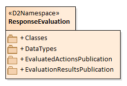
Figure 1 — The “VMS” namespace model
The “Vms” namespace shall include the following 5 packages:
- VmsTablePublication,
- VmsPublication,
- Classes,
- DataTypes,
- Enumerations.
The “Vms” package shall be immediately subordinate to the “PayloadPublication” package. It shall comprise the packages used in the VMS table publication and VMS publication as well as the “Classes”, “DataTypes” and “Enumerations” packages that are specific to these publications. They belong to the “D2Namespace” namespace “Vms”.
The classes, attributes, data types and enumerations that are specific to this document are defined in the normative Annex A.
The XML subschemas corresponding to this document is provided in the normative Annex B.
Some packages and individual classes used within the “Vms” package reside in the “D2Namespace” namespaces “Common”, “Location”, and “SituationPublication” because they can be used in different places within this package or by other packages. The named namespaces (D2Namespace) are a container for a number of packages and individual reusable classes. Those packages and classes, which are contained in the named namespaces, are identified in the following clauses. The use of these individual classes is only described in detail if their semantics in the VMS publications is altered.
NOTE “Common” namespace classes are defined in EN 16157-7, “Location” namespace classes are defined in EN 16157-2 and “SituationPublication” classes are defined in EN 16157-3.
Namespaces dependencies are shown in Figure 2.
NOTE Vms also has an potential indirect dependency on the Situation namespace through optional elements of type VersionedReference where the target elements are in the Situation namespace, i.e. there could be a dependency in implementing applications that try to access those references. This dependency is avoided if those optional elements are not used.
Figure 2 — The “VMS” namespace dependencies
The “VmsTablePublication” model
Overview of the “VmsTablePublication” model
The VMS Table Publication model shall comprise a top-level package, “VmsTablePublication” which utilises some classes from the “Classes” package.
The “VmsTablePublication” package shall model the usually static characteristics of VMS controllers and their controlled VMS.
Each “VmsTablePublication” class shall contain one or more “VmsControllerTable” class, each table containing a number of “VmsController” class which relate to deployed VMS controllers. These latter describe the deployed VMS controllers. Each “VmsController” shall contain one or more “Vms” objects, each of which relates to a specific VMS that is controlled by the VMS controller.
Although the characteristics of “Vms” and “VmsController” objects modelled in this publication are not updated frequently, sometimes these characteristics may change over time.
Other information updates changes may occur in the location of “VMS” objects when they are of a mobile type or in the number of lines of text if the sign supports variable font sizes. In these cases, some of the configuration information defined in this publication may be overridden by more up-to-date information disseminated in a “VmsPublication”. VMS configuration information provided in a “VmsPublication” shall always override any configuration information provided in the records of a “VmsTablePublication”.
The “VmsTablePublication” package
Overview of the “VmsTablePublication” package
The “VmsTablePublication” package shall comprise a sub-model for defining information describing the static characteristics of VMS controllers and their VMS (see Figure 3).
Each publication may contain one or more tables, allowing logical partitioning of VMS static information as deemed the most appropriate for recipients of VMS information by the supplier (e.g. by road designation or other geographic criteria or by type of VMS equipment etc.).
The corresponding class diagram is shown in Figure 3.
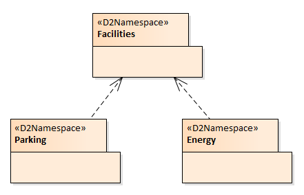
Figure 3 — The “VmsTablePublication” package class model
Semantics of the “VmsTablePublication” package
“VmsTablePublication” package semantics - general
The “VmsTablePublication” class shall be a specific realisable class as specialisation of “PayloadPublication”. Each “VmsTablePublication” may contain a number of separate VMS controller tables.
The information in the “VmsTablePublication” shall relate to the VMS controllers and their controlled VMS currently deployed on the road, and shall contain the static characteristics of those devices at a specified point in time. However, the characteristics and configuration of any VMS given in the “VmsTablePublication” shall be overridden by any corresponding characteristics and configuration that are given in a “VmsPublication” for the same VMS when those configuration and characteristics may be dynamically managed.
Some of the individual classes used within the “VmsTablePublication” package, principally those for modelling the characteristics of a VMS, also reside in the “VmsConfiguration” package which is within the “Classes” package as they are also used in the “VmsPublication” package”.
“VmsTablePublication” Class
The “VmsTablePublication” class shall be the top-level class for containing the published VMS controller tables.
“HeaderInformation” Class
Each instance of a “VmsTablePublication” shall have associated metadata contained in an instance of the “HeaderInformation” class which shall be used to specify how the recipient should treat the information contained in it. For “HeaderInformation” class refer to EN 16157-7.
“InternationalIdentifier” class
An international identifier may be associated to a VMS table to define which organisation manages its information. This class belongs to the “Common” package defined in EN 16157-7.
“VmsControllerTable” Class
An identifiable versioned instance of the “VmsControllerTable” class shall contain any logical collection of “VmsController”. A supplier may choose to provide a textual identification for a particular “VmsControllerTable” to clarify the logical collection of “VmsController”.
It may be possible to specify the organisation which manages the table information by the “informationManager” association to the “InternationalIdentifier” class.
“VmsController” Class
An identifiable versioned instance of the “VmsController” class shall contain the characteristics information relating to a specific VMS controller. Each record shall have one or more indexed “Vms” sub-records for containing the characteristics of the individual VMS that are controlled by the VMS controller. The “vmsIndex” qualifier provides a means for a given “VmsStatus” instance (in the VMS publication) to be referenced to the corresponding instance of the “Vms” class at the VMS controller.
“Vms” Class
An instance of the “Vms” class shall be used to provide the static characteristics of a VMS. The location of the VMS may be defined via the composition to “vmsLocation”. Any location that is managed by the VMS such as a car park or junction may be defined via a composition with the “VmsManagedLogicalLocation” class.
The “Location” class shall be used to identify details of the location where a VMS is physically situated or the location in which the VMS is logically considered to be located for its management, in case this is different from the physical location. The “Location” class and its components are defined in EN 16157-2.
The composition “imageLink” can be defined where a URL link can provide an image of the VMS. For “UrlLink” class refer to EN 16157-7.
The association to VmsConfiguration class allows specification of all static configuration information of the VMS. This information can be overridden by the configuration information which may be delivered in a VMS Status Publication through association to the same VmsConfiguration class which is described in the dedicated package clauses of this document (ref. subclause 4.2).
The VMS Publication model
Overview of the “VmsPublication” model
The VMS Publication model shall comprise a top-level package, “VmsPublication” and some sub-packages from the “Classes” package.
The “VmsPublication” package shall make use of a subordinate “VmsStatus” package and a “VmsMessage” package that together shall model the details of the status of variable message signs and what is currently displayed on them. The “VmsStatus” and “VmsMessage” packages shall reside in the “Classes” package of Vms namespace.
Each “VmsPublication” instance shall contain details of the status of every deployed VMS controller status, each of them controlling one or several VMS.
Some of the individual classes used within the “VmsPublication” package, principally those for modelling the characteristics of a VMS, are located in the “Classes” package as they are also used in the “VmsTablePublication” package”.
The “VmsPublication” package
Overview of the “VmsPublication” package
The “VmsPublication” package shall comprise the sub-model for defining a publication, which identifies the visual and textual content displayed on individual VMS and the status, and settings of those VMS, where each VMS is controlled by an associated VMS controller. The information shall be published in sets where each set relates to a particular VMS controller, which can control one or more VMS. The corresponding class diagram of the “VmsPublication” package is shown in Figure 4 .
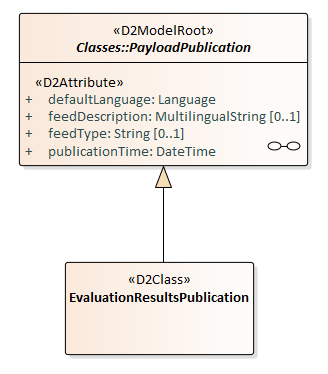
Figure 4 — The “VmsPublication” package class model
Semantics of the “VmsPublication” package
“VmsPublication” package semantics - general
The “VmsPublication” class shall be a specific realisable case of a “PayloadPublication”. Each “VmsPublication” may contain a number of separate sets of information, each relating to a set of VMS controllers and their controlled VMS.
The information related to each VMS controllers and their controlled VMS in the “VmsPublication” class, shall specify their status and the message or the messages that have actually been set on the VMS at a stated time.
NOTE The information in the “VmsPublication” relates to the current state of VMS controller and relative VMS deployed on the road, and not to any state information at the control centre, such as “pending” or “queued” or to any prioritised lists of messages which will be displayed at some point in the future.
“VmsPublication” Class
The “VmsPublication” class shall be the top-level class for containing the published VMS information.
“HeaderInformation” Class
Each instance of a “VmsPublication” shall have associated metadata contained in an instance of the “HeaderInformation” class which shall be used to specify how the recipient of the “VmsPublication” should treat the information contained in it. For “HeaderInformation” class refer to EN 16157-7.
The “Classes” package
Overview of the “Classes” package
This package contains all the packages and classes shared among the different publications of this document which are described in the following subclauses.
The “VmsConfiguration” package
Overview of the “VmsConfiguration” package
The “VmsConfiguration” package manages classes to provide information related to the VMS configuration which includes the settings and characteristics of VMS controllers and their controlled VMS which are deployed on the road network.
Each VMS controller controls one or more VMS which are a combination of textual, symbol or pictogram with optional supplementary panel display areas. Classes and their associations used to define this information are described in the “VmsConfiguration” class diagram in Figure 5.
For more details on some configuration aspects for full-matrix VMS see Annex C.
Figure 5 — The “VmsConfiguration” package class model
Semantics of the “VmsConfiguration” package
“VmsConfiguration” package semantics – general
The “VmsConfiguration” package shall comprise a “VmsConfiguration” class which has one or more indexed components where each component shall model the details of an individual display area related to all VMS component by composition to “DisplayArea” class.
A “DisplayArea” class may have an association to “Lane” to specify the lane to which the VMS is related when the associated lane is not specified, or it is different from what specified, by the VMS physical or managed location information. The associated lane can be defined both in VMS Table Publication when this association is considered static information or in VMS Publication when it is considered dynamic information.
A “DisplayArea” may be associated to one “DisplayGeometry” class which can be instantiated to define specific geometrical information of any display areas and their position in the overall VMS geometry.
“VmsConfiguration” class
The “VmsConfiguration” class provides the current configuration and characteristics information for the VMS which can be static or dynamically configured.
“DisplayArea” class
The “DisplayArea” class shall be used to define each individual display areas as they are configured for the VMS. A DisplayArea can be either generic or assigned to be a display area of a fixed type (text, pictogram or supplementary panel) through a specialisation.
Each display area on a VMS is referenced by its “displayAreaIndex” and it details its position relative to the VMS itself or its absolute position. As convention it is recommended to order the areas as they appear on the sign from left to right and top to bottom.
The DisplayArea class attributes allow the description of relative positional information among the various display by which the VMS is composed. Attribute “sequencingCapable” may be used to provide an indication of whether the VMS is capable to display multiple text pages, which are automatically displayed in a defined sequence and at a defined frequency rate. A maximum number of sequential pages may be specified by “maxNumberOfSequentialPages” attribute.
“Lane” class
The “Lane” class shall be used to supply information about the lane to which the VMS is associated. The “Lane” class and its components are defined in EN 16157-2.
“DisplayGeometry” class
The “DisplayGeometry” class shall be used to specify the geometric characteristics of a display area.
“TextDisplayArea” class
The “TexDisplayArea” class shall be used to describe the configuration characteristics of any text display area associated to the VMS, both as a static configuration instantiated at VMS Table publication or as dynamic configuration associated to a VMS status in a VMS publication. The characteristics for the text display area optionally include area dimensions (in pixels and metric measurements), font sizes, number of characters and rows, details of text area positioning on the VMS panel and the maximum luminance level.
The attribute “textCodeListIdentifier” may be used to identify what list of legends or texts are being used by the VMS. Usually specific deployments of VMS across a road network or part of a network will use defined sets of legends or texts which are specified by the road authority/operator and are consistent with the display capabilities of the specific VMS. This attribute allows the identity of this list to be disseminated.
“PictogramDisplayArea” class
The “PictogramDisplayArea” shall be used to describe the characteristics of any pictogram display area associated to the VMS.
The characteristics for the pictogram display area include area dimensions (in pixels and metric measurements), details of the positioning of the area on the VMS panel.
The attribute “pictogramCodeListIdentifier” may be used to identify what list of pictograms are being used by the VMS. Usually specific deployments of VMS across a road network or part of a network will use defined sets of pictograms which are specified by the road authority/operator and are consistent with the display capabilities of the specific VMS. This attribute allows the identity of this list to be disseminated.
“SupplementaryPanelArea” class
The “SupplementaryPanelArea” shall be used to describe the characteristics of any supplementary panel area associated with a specific pictogram area.
The “VmsStatus” package
Overview of the “VmsStatus” package
The package, “VmsStatus”, shall comprise a sub-model for defining information about the current settings, status, and characteristics of VMS controllers and their component VMS which are deployed on the road network.
Each VMS controller, as well as any of its controlled VMS, may be related to their current faults by the association with the VmsControllerFault class.
VMS may have a VMS configuration which eventually overrides the VMS configuration information provided in the VMS controller table associated. VMS may further be associated to a physical and managed logical location and shall contain one or more VMS messages which are displayed by the VMS display area(s).
NOTE Variable Message Sign (VMS) units are mostly static installations, but some may be mobile changing their locations from time to time.
The information about messages displayed by the VMS are described in the “VmsMessage” package (ref. clause 4.4 )
The “VmsStatus” class diagram is displayed in Figure 6.
Figure 6 — The “VmsStatus” package class model
Semantics of the “VmsStatus” package
“VmsStatus” package semantics - general
The “VmsStatus” package shall comprise a “VmControllerStatus” class which has one or more indexed components where each component shall model the details of an individual VMS that is controlled by the VMS controller.
The static characteristics of each VMS shall be identified by using an indexed reference into a specified object in a “VmsControllerTable” published in a “VmsTablePublication” (see clause 2). Alternatively, where VMS configuration can be set dynamically, these may be given directly in this publication, which, when provided, shall override any static characteristics defined in the referenced object in the “VmsControllerTable”.
“VmsControllerStatus” class
An instance of the “VmsControllerStatus” class shall represent the status of a single VMS controller at the roadside which may control one or more VMS. Through the “VmsControllerFault” class fault information can be associated with each “VmsController” class instance.
Each VMS controlled by a VMS controller is referenced by its “vmsIndex” qualifier. The “vmsIndex” qualifier provides an index into the specific “Vms” within the relevant “VmsController” (see VmsTablePublication in clause 2), from where the static VMS configuration information that are relevant for the VMS can be obtained. These VmsController instances are contained in a referenced VmsUnitTable that is published in a VmsTablePublication.
The attribute “vmsControllerTableReference” shall be used to provide a reference to an instance of a “VmsControllerTable” that is published in a “VmsTablePublication”. This reference shall point to the relevant table which holds the instance containing the details for this VMS controller.
The attribute “vmsControllerReference” shall be used to provide a reference to an instance of a “VmsController” within the referenced “VmsControllerTable” that is published in a “VmsTablePublication”.
An aggregation to a number of instances of the “VmsControllerFault” class allow to provide fault information relating to a variable message sign controller. More than one type of fault may exist at the same time. VmsControllerFault class information is described in the VmsFaultPackage description (see sub-clause 4.5.2.3.
“VmsStatus” class
An instance of the “VmsStatus” class shall represent a single VMS status which shall be used to define VMS dynamic configuration, any current fault status of the VMS and its message(s) displayed by VMS.
Each VMS has a location which can be defined in the referenced instance of a specific “VmsUnitTable” instance. Note that it is the location of the individual VMS which is to be provided, not the location of the VMS controller which controls them.
Where the location of a VMS is dynamic or has changed recently, the current location shall be provided as a composition (“vmsLocationOverride”) to the “VmsStatus” class instance, which shall override any location given in a referenced “VmsControllerTable”. Similarly, any location, which a VMS is used to manage such as a car park or a road junction, that has changed recently, can be provided via the “managedLogicalLocationOverride” composition, again, which shall override any managed location given in the relevant “VmsControllerTable” entry. The “Location” class and its components are defined in EN 16157-2.
An aggregation to a number of instances of the “VmsFault” class allow to provide fault information relating to the variable message sign. More than one type of fault may exist at the same time. VmsFault class information is described in the VmsFaultPackage description (see sub-clause 4.5.2.44.5)
An instance of the “VmsConfiguration” class through the vmsDynamicConfiguration association can be associated to the VMS Status, in the case the VMS characteristics information defined by the “VMSConfiguration” associated to the “VmsStatus” shall override any characteristics given in the referenced object of the “VmsUnitTable”.
A VMS may be set to display a sequence of messages in a defined order, where each message comprises a combination of text pages and/or pictograms. In this case, the “messageIndex” qualifier shall be used to distinguish the individual messages, their order of display and a messages sequencing interval (sequencingInterval attribute) may be specified to state the time frequency of the subsequent displayed messages. The VMS Message semantics is described in the “VmsMessage” package at subclause 4.44.4.
“ManagedLocation” Class
The “ManagedLocation” class shall be used to associate to a VMS the location (e.g. a car park, a section of road, a junction etc.), which the VMS contributes to manage. “Location” class associated as managed location and all its specialised and associated classes and their attributes are defined in EN 16157-2.
The “VmsMessage” package
Overview of the “VmsMessage” package
The “VmsMessage” package, shall comprise a sub-model for defining information about individual messages displayed on any VMS display areas which are described by the VMS configuration.
The VMS display areas configuration can be defined statically in a VMS table publication by the VMSConfiguration class and relative package for fixed display VMS, while full matrix VMS, which allows a dynamic configuration and usage of the full matrix VMS display area, can dynamically set several different areas of the VMS to display textual or pictogram information. In these cases, the VMS overall display results as a dynamic composition of textual and graphic information which need to be assessed in real time by “VMSConfiguration” information.
Each text message component shall comprise one or more text pages. Each pictogram message component shall comprise one or more pictograms each with possible additional supplementary information or regulatory instructions that qualify the displayed pictogram. In case of multiple text pages and/or pictograms, those pages shall be sequenced in a specified order and at a specified interval which can be specified.
The “VmsMessage” class diagram is shown in Figure 7 and the Pictogram class diagram is shown in Figure 7.
Figure 7 — The “VmsMessage” class diagram
Semantics of the” VmsMessage” package
“VmsMessage” package semantics - general
The “VmsMessage” package shall comprise a “VmsMessage” class which has a number of indexed display area settings specialised for each one of the individual display areas defined at VMS configuration.
Display area settings can implement multipage or single page text displays, which are structured in one or more “single line text” areas, or a number of pictograms with optional supplementary information displayed in one or more pictograms including their possible supplementary panel display.
Where multiple pages are specified for display, either in the text or pictogram display area, the order in which they are displayed is identified by the “pageNumber” qualifier order. In this case the “sequencingInterval” attribute on the “VmsMessage” class may be specified to describe the time interval used for page sequencing.
Each text page is described by the sequence of its text lines which display a text line string which can be related to one or more information significant to road users.
For each pictogram display area used by a VMS message, a sequence of separate pictograms may be specified as being displayed in that area. Each of the pictograms may be associated to a supplementary information display which can be displayed by the relative supplementary panel area.
The supplementary information display can be used to display one line of text or a graphics represented by a supplementary pictogram.
Pictogram graphic information with optional supplementary information can be represented by a GDD coding when available. Pictograms which are not managed in GDD can be specified by a description which is defined in specialised classes for regular and composite pictograms. Numerical information, up to 2 numbers, associated to a pictogram shall be managed by specific displayed numerical information class.
“VmsMessage” Class
An instance of the “VmsMessage” class, which is referenced by its “messageIndex” qualifier by the “VmsStatus” class, shall be used to identify the details of the message currently being displayed on the VMS’s text display areas, the various pictogram display areas as well as the supplementary panel display areas, which may exist to support the pictogram display areas, as described by the VMS VMSConfiguration, both at VMS table publication or at VMS Status.
The “messageIndex” qualifier on the association with the “VmsStatus” class shall indicate the order of display of the messages if there are multiple messages specified, the sequence continuously cycling. If there is only one message being displayed the “messageIndex” shall have a value of “1”. When a VMS displays several messages a sequencing interval can be specified to express the time frequency messages are displayed one after the other.
A combination of message information type may be associate to the VMS message to specify the main information displayed by the message. A coded reason for setting can be used to express the main purpose of the message e.g. situation related information, campaign, default message (i.e. no road related information), etc.
When message information is related to a specific situation or situation record, this may be specified by setting the corresponding attribute “situationReference” and “situationRecordReference” which shall contain respectively the reference to the specific situation or the versioned reference to the specific situation record, to which the message is related. This reference information shall be related to “Situation” and “SituationRecord” classes which are defined in EN 16157-3.
A VMS message is associated to the VMS display area settings through an indexed association identified by displayAreaIndex number which shall match the number used to specify the corresponding display areas in VMS configuration. Where a “SupplementaryInformationDisplay” instance is supplied as subordinate to a “PictogramDisplay” instance, it shall not be repeated in this collection.
An image can be associated to the “VmsMessage” by association to “Image” class, which represent the overall VMS information displayed on the VMS as an image.
“DisplayAreaSettings” Class
A “DisplayAreaSetting” class shall be used to define the display of any VMS configuration component and is specialised in one of the “TextDisplay”, “MultiPageDisplay”, “PictogramDisplay”, “SupplementaryInformationDisplay” classes.
Where a “SupplementaryInformationDisplay” instance is supplied as subordinate to a “PictogramDisplay” instance, it should not be repeated in this collection.
When the display area is set to blank, i.e. it shows no information, the related “isBlank” attribute shall be set to true.
“MultiPageDisplay”
The “MultiPageDisplay” class shall be used to describe a display, either text or pictogram display, which shows multiple pages across time, sequentially displayed in order of their “pageNumber”. Sequencing, if used, shall be assumed to continuously cycle through the ordered display pages at a constant rate (the corresponding sequencing interval can be specified in the “VmsMessage” class).
The “pageNumber” qualifier shall be used to indicate the order of sequencing of the pages of display, the value of “1” indicating the first page.
“TextDisplay” Class
An instance of the “TextDisplay” class shall be used to identify what text is displayed in the text display area, or as part of a multi-page display, and what it looks like on the VMS. Where multiple lines of text are defined each is referenced by its “lineIndex” qualifier and is ordered accordingly
The attribute “vmsTextCode” shall identify the code of the text from the text code list referenced in the “TextDisplayArea” class (see subclause 4.2.2.6). Typically, this will use the individual road authority’s/operator’s coding scheme for the different text messages.
Line break detail is specified by providing an indexed sequence of instances of the “TextLine” class, which gives the actual text strings for each line.
“TextLine” class
An instance of the “TextLine” class shall be used to identify what text is displayed on a single line in the text display area, or in the supplementary text related to supplementary information display. It also allows the language and the colour of the text line to be specified, and whether it is flashing or has any special formatting applied to it. Each line of text coded as a string is used to give the evidence of the exact text which is displayed on the VMS text line. This text is exact except when special characters are used which can implement non language character symbols: based on this option the “isExactTextOnSign” attribute can be set to express when “textLine” string is the exact text displayed or not.
When needed the text line language can be specified for each of the text lines displayed. Text information type may be set to address a multiplicity of coded information type which are described in the single text line, e.g. location, destination, situation, etc.
The “lineIndex” qualifier shall be used to indicate the order of the lines of text, the value of “1” indicating the top or first line of the text.
“PictogramDisplay” class
An instance of the “PictogramDisplay” class shall be used for association to a pictogram that is being displayed on a specific pictogram display which is configured for the VMS, both as single pictogram display or as part of a multi-page display.
When a pictogram display is the primary pictogram information, by application level rules or VMS Message general understanding, this may be specified by setting the corresponding “isPrimaryPictogram” attribute.
An “Image” class instance can be associated to the “PictogramDisplay” which represent the graphical displayed pictogram as an image.
“Pictogram” class
An instance of the “VmsPictogram” class shall be used to identify the pictogram graphics which is currently displayed, in the specified pictogram display area configured for the VMS.
The relationship among Pictograms and its specialised and aggregate class is shown in figure 8 .
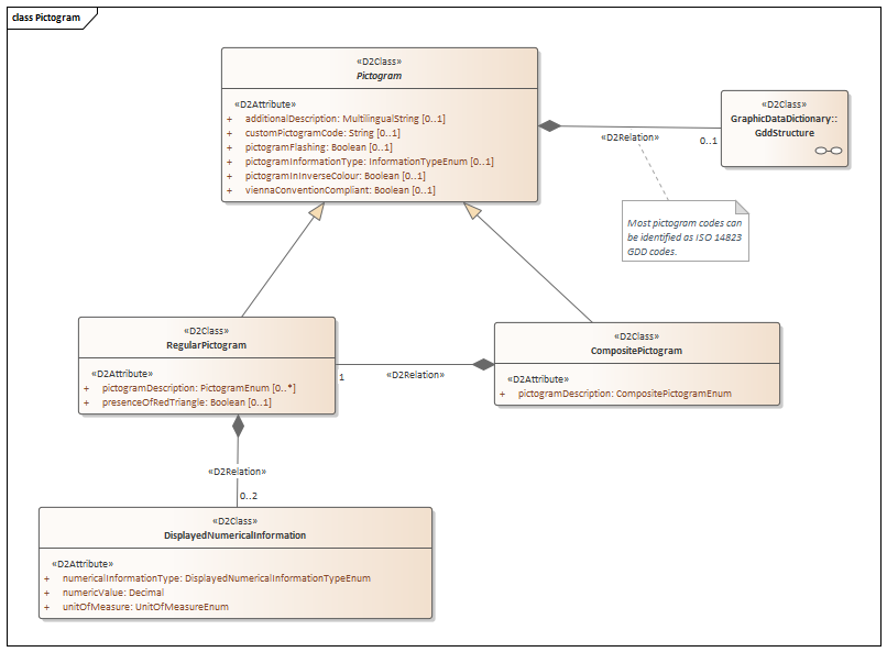
Figure 8 — The “Pictogram” class diagram
A pictogram can be either a regular pictogram which is intended to provide one specific graphics, but it can be also a composite pictograms which combines 2 different kind of graphics to enable description of specific road topology configuration where a pictogram information can be relevant, e.g. on the exit, after the next exit combined with any regular pictogram, such as roadworks or network restrictions.
A pictogram should be coded by GDD using the related association to “GDDStructure” class, which is fully described in sub-clause 4.6.2.2. When the GDD code is not defined for the pictogram, besides the coded description managed in “RegularPictogram” and “CompositePictogram” classes which enable to specify some general pictograms which had not been coded in GDD, an extra textual description of the displayed pictogram can be set by the “additionalDescription” attribute and a custom pictogram code can be specified as string.
“RegularPictogram” class
An instance of the “RegularPictogram” class shall be used to describe a regular pictogram. A “pictogramDescription” attribute may be used to address a non GDD pictogram among a list of predefined pictogram (see PictogramEnum at Annex A.4.11).
Up to 2 numerical information can be associated to pictogram, e.g. as speed limit or distance, this information can be addressed by the specific “DisplayedNumericalInformation” class.
“DisplayedNumericalInformation” class
An instance of the “DisplayedNumericalInformation” shall be used to describe the numerical information associated to a regular pictogram and its unit of measure (e.g. speed expressed as km/h or miles/h).
“CompositePictogram” class
An instance of the “CompositePictogram” class shall be used to describe a composite pictogram. A pictogramDescription attribute may be used to to specify the composite pictogram type among a list of predefined pictogram (see CompositePictogramEnum at Annex A.4.3).
“SupplementaryInformationDisplay” class
An instance of the “SupplementaryInformationDisplay” class shall be used to identify what is displayed on the panel which is supplementary to a pictogram display (generally below it). A supplementary panel can display one and only one line of text or a single supplementary pictogram. The textual description of what is displayed in the supplementary panel as a single line text may be provided by association to the “SupplementaryText” class.
“SupplementaryPictogram” class
An instance of the “SupplementaryPictogram” class shall be used to identify what pictogram is displayed on the supplementary panel. This will generally be one from a limited set i.e. from a list of supplementary pictogram description.”SupplementaryText” class
An instance of the “SupplementaryText” class shall be used to specify one and only one text line which is displayed in a supplementary information display associated with a pictogram, by its association to the “TextLine” class.
“Image” class
An instance of “Image” class shall be used to specify an image by the exact image binary content, coded as base 64, in any of the available commonly used image formats allowed.
The attribute “imageData” contains the image binary information coded as base 64 binary.
The attribute “imageFormat” specifies which format is used to encode the image, e.g. gif, png, bmp, tiff formats.
The “VmsFault” package
Overview of the “VmsFault” package
The “Fault package” is introduced to manage reusable classes to provide information related to fault for equipment and devices. Classes related to Vms are VmsFault and VmsUnitFault are displayed in figure 9 .
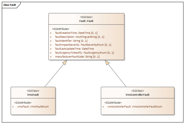
Figure 9 — The “Fault” package class model
Semantics of the “VmsFault” package
“VmsFault” package semantics – general
This package describes information about faults for only VMS and VMS controllers.
“Fault” class
The “Fault” class shall be used to supply information about a fault relating to a specific piece of equipment or process. The “Fault” class and its components are defined in EN 16157-7.
“VmsControllerFault” class
The “VmsControllerFault” class shall be used to provide information of faults related to VMS controllers. Each instance of a “VmsControllerFault” inherits fault details from the “Fault” class, which, at a minimum, shall contain the time that the fault information was last updated.
“VmsFault” Class
The “VmsFault” class shall be used to provide information of faults related to VMS. Each instance of a “VmsFault” inherits fault details from the “Fault” class, which, at a minimum, shall contain the time that the fault information was last updated.
The “GraphicDataDictionary” package
Overview of the “GraphicDataDictionary” package
The “Graphic Data Dictionary” package manages reusable classes to provide information related to objects which can describe pictogram information according to methodology and coding rules specified by the EN ISO 14823. This “Graphics Data Dictionary” (GDD) allows identification of pictograms for equipment and devices. Classes related to GDD are “GddStructure”, “GddPictogramDefinition” and “GddPictogramIdentification” as illustrated in figure 10 .
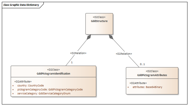
Figure 10 — The “Graphic Data Dictionary” package class model
Semantics of the “GraphicDataDictionary” package
“GraphicDataDictionary” package semantics – general
DD, as defined in EN ISO 14823, identifies a pictogram by using a structured code through use of subcoding split into a “service category” and a “pictogram category” code, further a “country” code, as the reference country of the pictogram category code, which is used for distinguishing nationally allocated codes which can have different meaning. GDD also allows coding of further specific information (e.g. maximum speed limit, vehicle gross weight limit, etc.) which can be addressed further as defined in EN ISO 14823.
“GddStructure” class
The “GddStructure” class shall be used to provide the GDD coding. This class is associated through mandatory composition to “GddPictogramDefinition”, so a GDDPictogramDefinition shall be instantiated to address a pictogram GDD reference, and optional “GddPictogramAttributes” class can be instantiated to provide binary encoded GDD attributes when needed.
“GddPictogramIdentification” class
The “GddPictogramIdentification” class shall be used to encode the structured GDD code information provided by country, service and pictogram category as defined in EN ISO 14823.
“GddPictogramAttributes” class
The “GddPictogramAttributes” class may provide optional GDD attributes associated to the graphical sign by the “attributes” attribute as defined in EN ISO 14823. This attribute list information is defined as binary encoded list where the encoding shall follow unaligned packed encoding rules (UPER) [ISO/IEC 8825-2:2015]