Use of ALERT-C location referencing system¶
See also EN ISO 14819-3:2004
Introduction¶
These rules are proposed to be used with method 4 (see § 4.18.1 boven) that consists in providing ALERT-C point locations bracketing the element and distances from these points and the actual points.
Method 2 is similar to method 4 but does not include offsets and thus the rules for offset do not apply.
The positive direction corresponds to the point (and segment when it exists)) order when going from the first point to the last point using positive offsets. It is named “AlertC chaining” in the pictures of the following examples. It fits the corresponding road direction defined as going from its first name to its second name.
For syntax, the user-defined values (between tags) are given within square brackets whereas the variable parameters (within a tag) are italicised. When a value between tags is in roman, it means the value comes from a predefined enumeration. When the possible values are all mentioned, the first follows the previous rule where as the others are in brackets, comma-separated.
Definitions for Method 4¶
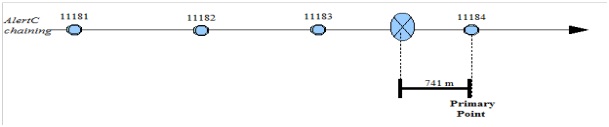
The primary point is the first ALERT-C point location after the head of the event in relation to the traffic direction.
The primary point offset is the (positive) distance between the head of the event and the primary point.
The secondary point is the first ALERT-C point location before the tail of the event in relation to the traffic direction.
The secondary point offset is the (positive) distance between the tail of the event and the secondary point.
The event direction, i.e. the corresponding traffic direction is given in related to the ALERT-C points chaining order: P: Positive, N: Negative, B: in both directions.
Information concerning the primary point is mandatory for all events.
Information concerning the secondary point is mandatory for linear events but optional for point events. (i.e. for space-limited locations)
Note
Head and tail of an event are defined according to the usual congestion terminology.
Note
An accident generally is on a point but may be of some extend and thus linear.
Syntax in XML¶
<alertCLinear xsi:type="AlertCMethod4Linear">
    <alertCLocationCountryCode>[F]</alertCLocationCountryCode>
    <alertCLocationTableNumber>[32]</alertCLocationTableNumber>
    <alertCLocationTableVersion>[alertC table version]</alertCLocationTableVersion>
    <alertCDirection> (i.e. Event direction)
        <alertCDirectionCoded>both (positive, negative)</alertCDirectionCoded>
    </alertCDirection>
    <alertCMethod4PrimaryPointLocation>
        <alertCLocation>
            <alertCLocationName>
                <value lang="fr">[Name of primary point]</value>
            </alertCLocationName>
        <specificLocation>[Primary point identifier]</specificLocation>
        </alertCLocation>
        <offsetDistance>
            <offsetDistance>[Offset of primary point]</offsetDistance>
        </offsetDistance>
    </alertCMethod4PrimaryPointLocation>
    <alertCMethod4SecondaryPointLocation>
        <alertCLocation>
            <alertCLocationName>
                    <value lang="fr">[Name of secondary point]</value>
            </alertCLocationName>
        <specificLocation>[Secondary point identifier]</specificLocation>
        </alertCLocation>
        <offsetDistance>
            <offsetDistance>[Offset of secondary point]</offsetDistance>
        </offsetDistance>
    </alertCMethod4SecondaryPointLocation>
</alertCLinear>
Note
The above also goes for AlertCMethod4Point, not just for AlertCMethod4Linear
To simplify examples presentation, the following part of the syntax is not duplicated:
<alertCLocationCountryCode>[country code]</alertCLocationCountryCode>
<alertCLocationTableNumber>[table number]</alertCLocationTableNumber>
<alertCLocationTableVersion>[ table version]</alertCLocationTableVersion>
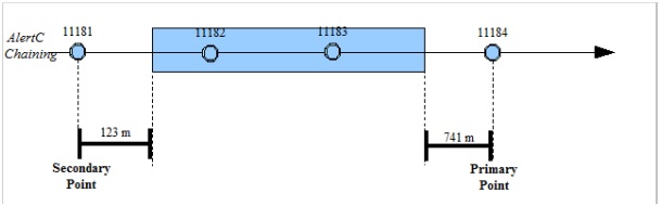
Example 1: Case of positive direction for a linear event¶
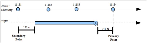
<alertCLinear xsi:type="AlertCMethod4Linear">
    <alertCDirection>
        <alertCDirectionCoded>positive</alertCDirectionCoded>
    </alertCDirection>
    <alertCMethod4PrimaryPointLocation>
        <alertCLocation>
            <alertCLocationName>
                <value lang="fr">Sémecourt</value>
            </alertCLocationName>
            <specificLocation>11184</specificLocation>
        </alertCLocation>
        <offsetDistance>
            <offsetDistance>741</offsetDistance>
        </offsetDistance>
    </alertCMethod4PrimaryPointLocation>
    <alertCMethod4SecondaryPointLocation>
        <alertCLocation>
            <alertCLocationName>
                <value lang="fr">Aire de Metz Saint-Privat</value>
            </alertCLocationName>
            <specificLocation>11181</specificLocation>
        </alertCLocation>
        <offsetDistance>
            <offsetDistance>123</offsetDistance>
        </offsetDistance>
    </alertCMethod4SecondaryPointLocation>
</alertCLinear>
Example 2: Case of positive direction for a point event¶
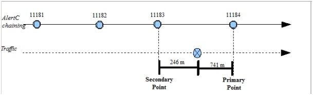
<alertCLinear xsi:type="AlertCMethod4Point">
    <alertCDirection>
        <alertCDirectionCoded>positive</alertCDirectionCoded>
    </alertCDirection>
    <alertCMethod4PrimaryPointLocation>
        <alertCLocation>
            <alertCLocationName>
                <value lang="fr">Sémecourt</value>
            </alertCLocationName>
           <specificLocation>11184</specificLocation>
        </alertCLocation>
        <offsetDistance>
            <offsetDistance>741</offsetDistance>
        </offsetDistance>
    </alertCMethod4PrimaryPointLocation>
</alertCLinear>
Example 3: Case of negative direction for a linear event¶
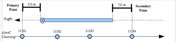
    <alertCLinear xsi:type="AlertCMethod4Linear">
    <alertCDirection>
        <alertCDirectionCoded>negative</alertCDirectionCoded>
    </alertCDirection>
    <alertCMethod4PrimaryPointLocation>
        <alertCLocation>
            <alertCLocationName>
                <value lang="fr">Aire de Metz Saint-Privat</value>
            </alertCLocationName>
            <specificLocation>11181</specificLocation>
        </alertCLocation>
        <offsetDistance>
            <offsetDistance>123</offsetDistance>
       </offsetDistance>
    </alertCMethod4PrimaryPointLocation>
    <alertCMethod4SecondaryPointLocation>
        <alertCLocation>
            <alertCLocationName>
                <value lang="fr">Sémecourt</value>
            </alertCLocationName>
            <specificLocation>11184</specificLocation>
        </alertCLocation>
        <offsetDistance>
            <offsetDistance>741</offsetDistance>
        </offsetDistance>
    </alertCMethod4SecondaryPointLocation>
</alertCLinear>
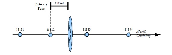
Example 4: Case of negative direction for a point event¶
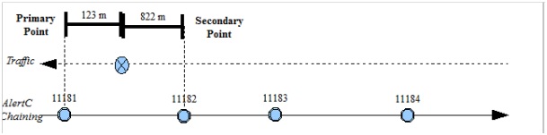
<alertCLinear xsi:type="AlertCMethod4Point">
    <alertCDirection>
        <alertCDirectionCoded>negative</alertCDirectionCoded>
    </alertCDirection>
    <alertCMethod4PrimaryPointLocation>
        <alertCLocation>
            <alertCLocationName>
                <value lang="fr">Aire de Metz Saint-Privat</value>
            </alertCLocationName>
            <specificLocation>11181</specificLocation>
        </alertCLocation>
        <offsetDistance>
            <offsetDistance>123</offsetDistance>
        </offsetDistance>
    </alertCMethod4PrimaryPointLocation>
</alertCLinear>
Example 5: Case of both directions for a point event¶
In such case the traffic direction is not be taken into account.
But the Primary point should be always determined using the positive direction.
This event is located as follows:
<alertCLinear xsi:type="AlertCMethod4Point">
    <alertCDirection>
        <alertCDirectionCoded>positive</alertCDirectionCoded>
    </alertCDirection>
    <alertCMethod4PrimaryPointLocation>
        <alertCLocation>
            <alertCLocationName>
                <value lang="fr">Sémecourt</value>
            </alertCLocationName>
           <specificLocation>11184</specificLocation>
        </alertCLocation>
        <offsetDistance>
            <offsetDistance>741</offsetDistance>
        </offsetDistance>
    </alertCMethod4PrimaryPointLocation>
</alertCLinear>
Important remark
Note that in case a previous version of this event was coded as one-direction event, the primary point location would be the same for the positive direction .If the previous version was coded in the negative direction, the primary point location would be moved from 11183 (previous version) to 11184 (version in both direction).
If the primary point is not taken by reference to positive direction, there may be a misunderstanding by the client system as explained below:
The supplier application only generates the Primary point, based on the negative direction:
The client application interprets this message using the positive direction:
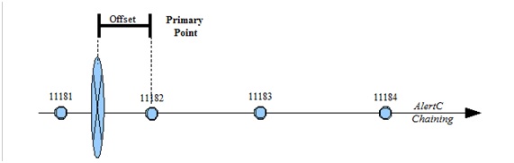
The event is thus shifted by twice the offset from its true position, often several kilometres.
Example 6: Case of both directions for a linear event¶
In such case the traffic direction is not taken into account.
However, the Primary point should be determined using the positive direction. This choice corresponds with the case of Point event, even if there is no risk of wrongly locating the event between supplier and client.
This event is located as follows:
<alertCLinear xsi:type="AlertCMethod4Linear">
    <alertCDirection>
         <alertCDirectionCoded>both</alertCDirectionCoded>
    </alertCDirection>
    <alertCMethod4PrimaryPointLocation>
        <alertCLocation>
            <alertCLocationName>
                <value lang="fr">Sémecourt</value>
            </alertCLocationName>
            <specificLocation>11184</specificLocation>
        </alertCLocation>
        <offsetDistance>
            <offsetDistance>741</offsetDistance>
        </offsetDistance>
    </alertCMethod4PrimaryPointLocation>
    <alertCMethod4SecondaryPointLocation>
        <alertCLocation>
            <alertCLocationName>
                <value lang="fr">Aire de Metz Saint-Privat</value>
            </alertCLocationName>
            <specificLocation>11181</specificLocation>
        </alertCLocation>
        <offsetDistance>
            <offsetDistance>123</offsetDistance>
        </offsetDistance>
    </alertCMethod4SecondaryPointLocation>
</alertCLinear>
Use of linear location referencing system¶
Introduction¶
These rules are proposed to be used in case of linear referencing systems. They may be absolute, relative, i.e. based on referents, or interpolative, i.e. expressed by a percentage along the linear element (see paragraph XXX).
For syntax, the user-defined values (between tags) are given within square brackets whereas the variable parameters (within a tag) are italicised. When a value between tags is in roman, it means the value comes from a predefined enumeration. When the possible values are all mentioned, the first follows the previous rule where as the others are in brackets, comma-separated.
A linear reference is always attached to a linear element: it can be a predefined whole road or a continuous road section. It can also be defined as a link-node sequence with its nodes or reference posts. In this latter case a referent shall be given for both extremities.
The direction of an underlying linear element is defined by the referent (i.e. node) sequence according to the sequence order. Generally, each referent has a one-to-one relationship with the consequent referent (or sometimes with the previous one). When using a link–node graph for underlying linear elements, the link direction (supposed to be oriented) is the reference direction.
Unlike the ALERT-C location referencing system, the traffic event does not have an influence on the way to define the corresponding location. Only one of the corresponding direction attributes of the location is dealt with.
Even if the corresponding attributes are not mandatory it is very wise to give either the road number if it exists or by default its name.
Todo
Add link
Definitions¶
The “from” point of a linear is the first encountered point delineating a linear location according to the direction of the underlying linear element.
The “to” point of a linear is the last encountered point delineating a linear location according to the direction of the underlying linear element.
The distance is the curvilinear abscissa measured between the measure origin and the considered point. It is positive when it is made following the same direction as the one of the underlying element except for the interpolative method.
For the interpolative method the distance is expressed as a percentage between the curvilinear abscissa from the origin and the total linear element length.
Note
An accident is generally a point event but may be of significant length in some cases and thus linear (example of a pile-up).
Note
According to the Datex II specifications, the event direction can be given either geographically (“directionBound”) or by comparing the underlying element direction (“directionRelative”).
All examples below use road as underlying linear element, its direction and its road number.
XML syntax for a point location¶
<pointAlongLinearElement>
    <directionRelativeAtPoint>[aligned/opposite/both]</directionRelativeAtPoint>
    <linearElement>
        <roadNumber>[Road number]</roadNumber>
    [Definition of this element either by a code or by a set a points – see below]
    </linearElement>
    <distanceAlongLinearElement xsi:type="DistanceFromLinearElementReferent">
        <distanceAlong>[Distance from referent]</distanceAlong>
        <fromReferent>
            <referentIdentifier>[Referent identifier]</referentIdentifier>
            <referentType>referenceMarker, (border, …)</referentType>
        </fromReferent>
    </distanceAlongLinearElement>
</pointAlongLinearElement>
XML syntax for a linear location¶
<linearWithinLinearElement>
    <directionRelativeOnLinearSection>[aligned/opposite/both]</directionRelativeOnLinearSection>
    <linearElement>
        <roadNumber>[Road number]</roadNumber>
    </linearElement>
    <fromPoint xsi:type="DistanceFromLinearElementReferent">
        <distanceAlong>[Distance from first referent]</distanceAlong>
        <fromReferent>
            <referentIdentifier>[First referent identifier]</referentIdentifier>
            <referentType>referenceMarker, (border,…)</referentType>
        </fromReferent>
    </fromPoint>
    <toPoint xsi:type="DistanceFromLinearElementReferent">
        <distanceAlong>[Distance from second referent]</distanceAlong>
        <fromReferent>
            <referentIdentifier>{Second referent identifier]</referentIdentifier>
            <referentType>referenceMarker, (border,…)</referentType>
        </fromReferent>
    </toPoint>
</linearWithinLinearElement
Example 1: Case of aligned direction for a point event¶
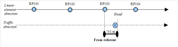
This event is located as follows:
A point accident located using a “fromReferent” RP103, a 741-metre abscissa and a aligned direction.
In case the event is in the opposite direction or in both directions the attribute “directionRelativeAtPoint” is modified accordingly. All the other elements / attributes are unmodified.
Example 2: Case of aligned direction for a linear event¶
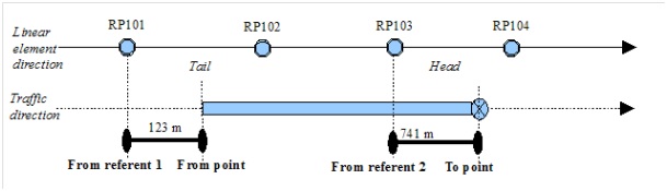
This event is located as follows:
Congestion is located linearly with an aligned direction, a “from point” using the “from referent” RP101 and a 123-metre abscissa, a “to point” using the “from referent” RP103 and a 741-metre abscissa.
In case the event is in the opposite direction or in both directions the attribute “directionRelativeOnLinearSection” is modified accordingly. All the other elements / attributes are unmodified.
Example 3: Case of direction defined by two referents for a point event¶
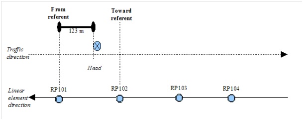
This event is located as follows:
Point accident with point located using a “from referent” RP101, a “toward referent” RP102, a direction going from RP101 to Rp102, a relative direction positive and a 123-metre abscissa measured from RP101.
Definition of the underlying linear element¶
As already stated above, the underlying linear element may be defined with a reference (code) to an external database which contains predefined linear elements e.g. links or GDF road elements.
The other possibility is to define “on the fly” this linear element as an ordered sequence of referents, the first one being placed at the start point of this element and the last one at the end point. The corresponding syntax is the following (case of an intermediate point for this element):
<linearElement xsi:type="LinearElementByPoints">
    <roadNumber>[Road number]</roadNumber>
    <linearElementNature>road, roadSection, slipRoad, other</linearElementNature>
    <startPointOfLinearElement>
        <referentIdentifier>[First referent identifier]</referentIdentifier>
        <referentType>boundary, referenceMarker, …</referentType>
    </startPointOfLinearElement>
    <intermediatePointOnLinearElement index="1">
        <referent>
            <referentIdentifier>[Intermediatet referent identifier]</referentIdentifier>
            <referentType>boundary, referenceMarker, …</referentType>
        </referent>
    </intermediatePointOnLinearElement>
    <endPointOfLinearElement>
        <referentIdentifier>[Last referent identifier]</referentIdentifier>
        <referentType>boundary, referenceMarker, …</referentType>
    </endPointOfLinearElement>
</linearElement>
Use of TPEG location referencing system¶
Introduction¶
This part describes the minimum attribute set of TPEG location. This location type can be used extensively but as it is based on geographic map make sure that the client is able to understand all the attributes.
For syntax, the user-defined values (between tags) are given within square brackets whereas the variable parameters (within a tag) are italicised. When a value between tags is in roman, it means the value comes from a predefined enumeration. When the possible values are all mentioned, the first follows the previous rule where as the others are in brackets, comma-separated.
Definitions¶
-The head of the event is defined as the point where the generating factor of the event is situated.
For example, in a traffic jam, the head is the point where traffic flows normally again after travelling through the congestion. The tail is situated at the point where the vehicle begins to slow down and enters the congestion.
Unlike the ALERT-C location referencing system, the event is not defined between two referent points, but at a precise, independent position.
In case of an isolated event, only the corresponding point is described with its direction.
In case of a linear event, only the start and end points of the event are described. Direction is also given.
TPEG referencing is based on a large number of classes, most of which are optional. The following chapter describes some implementation choices of these classes for a minimum use of TPEG.
As for the ALERT-C and linear referencing locations, a TPEG location in DATEX II must be contained within the tags:
    <locationReference>
        ...
    </ locationReference>

.. note:: The following syntaxes and examples are based on non-junction points. However the principle can be adapted to cover the case of junction points.
XML syntax for a point location¶
In case of a point event, the Datex II syntax is as follows:
<locationReference>
    <locationContainedInGroup xsi:type="ns1:Point">
        <tpegPointLocation xsi:type="ns1:TPEGSimplePoint">
            <tpegDirection>[cardinal direction]</tpegDirection>
            <tpegSimplePointLocationType>nonLinkedPoint</tpegSimplePointLocationType>
            <point xsi:type="ns1:TPEGNonJunctionPoint">
                <pointCoordinates>
                    <latitude>[latitude]</latitude>
                    <longitude>[longitude]</longitude>
                </pointCoordinates>
                <name>
                    <descriptor>
                        <value lang="lang">[Name of town]</value>
                    </descriptor>
                    <tpegOtherPointDescriptorType>
                        townName
                    </tpegOtherPointDescriptorType>
                </name>
                <name>
                    <descriptor>
                        <value lang="lang">[Name of road]</value>
                    </descriptor>
                    <tpegOtherPointDescriptorType>
                        linkName
                    </tpegOtherPointDescriptorType>
                </name>
            </point>
        </tpegpointLocation>
    </locationContainedInGroup>
</locationReference>
Note
The attribute “tpegSimplePointLocationType” may have one the following two values depending on the location type: “junctionPoint” (when located on an intersection) and “nonLinkedPoint” (otherwise). On a junction the value “junctionPoint” shall be used and either the junction name or the names of the intersecting roads (3 maximum) shall be given.
XML syntax for a linear location¶
In case of a linear event, two points are described with the DATEX II syntax below. The point “to” corresponds with the head of the event. The point “from” corresponds to the tail of the event.
<locationReference>
<locationContainedInGroup xsi:type="ns1:Linear">
    <tpegLinearLocation>
        <tpegDirection>[cardinal direction]</tpegDirection>
    <tpegLocationType>segment</tpegLocationType>
    <to xsi:type="ns1:TPEGNonJunctionPoint">
        <pointCoordinates>
            <latitude>[latitude at head]</latitude>
            <longitude>[longitude at head]</longitude>
        </pointCoordinates>
        <name>
            <descriptor>
                <value lang="lang">[Name of town at head]</value>
            </descriptor>
            <tpegOtherPointDescriptorType>
                townName
            </tpegOtherPointDescriptorType>
        </name>
        <name>
            <descriptor>
                <value lang="fr">[Name of road at head]</value>
            </descriptor>
            <tpegOtherPointDescriptorType>
                linkName
            </tpegOtherPointDescriptorType>
        </name>
    </to>
    <from xsi:type="ns1:TPEGNonJunctionPoint">
        <pointCoordinates>
            <latitude>[latitude at tail]</latitude>
            <longitude>[longitude at tail]</longitude>
        </pointCoordinates>
        <name>
            <descriptor>
                <value lang="lang">[Name of town at tail]</value>
            </descriptor>
            <tpegOtherPointDescriptorType>
                townName
            </tpegOtherPointDescriptorType>
        </name>
        <name>
            <descriptor>
                <value lang="lang">[Name of road at tail]</value>
            </descriptor>
            <tpegOtherPointDescriptorType>
                linkName
            </tpegOtherPointDescriptorType>
        </name>
    </from>
</tpegLinearLocation>
</locationContainedInGroup>
</locationReference>
Expression of latitude and longitude¶
These are expressed in decimal degrees in the European Terrestrial Reference System 1989 (ETRS89) which complies with ITRS, thus the values are considered as being equivalent.